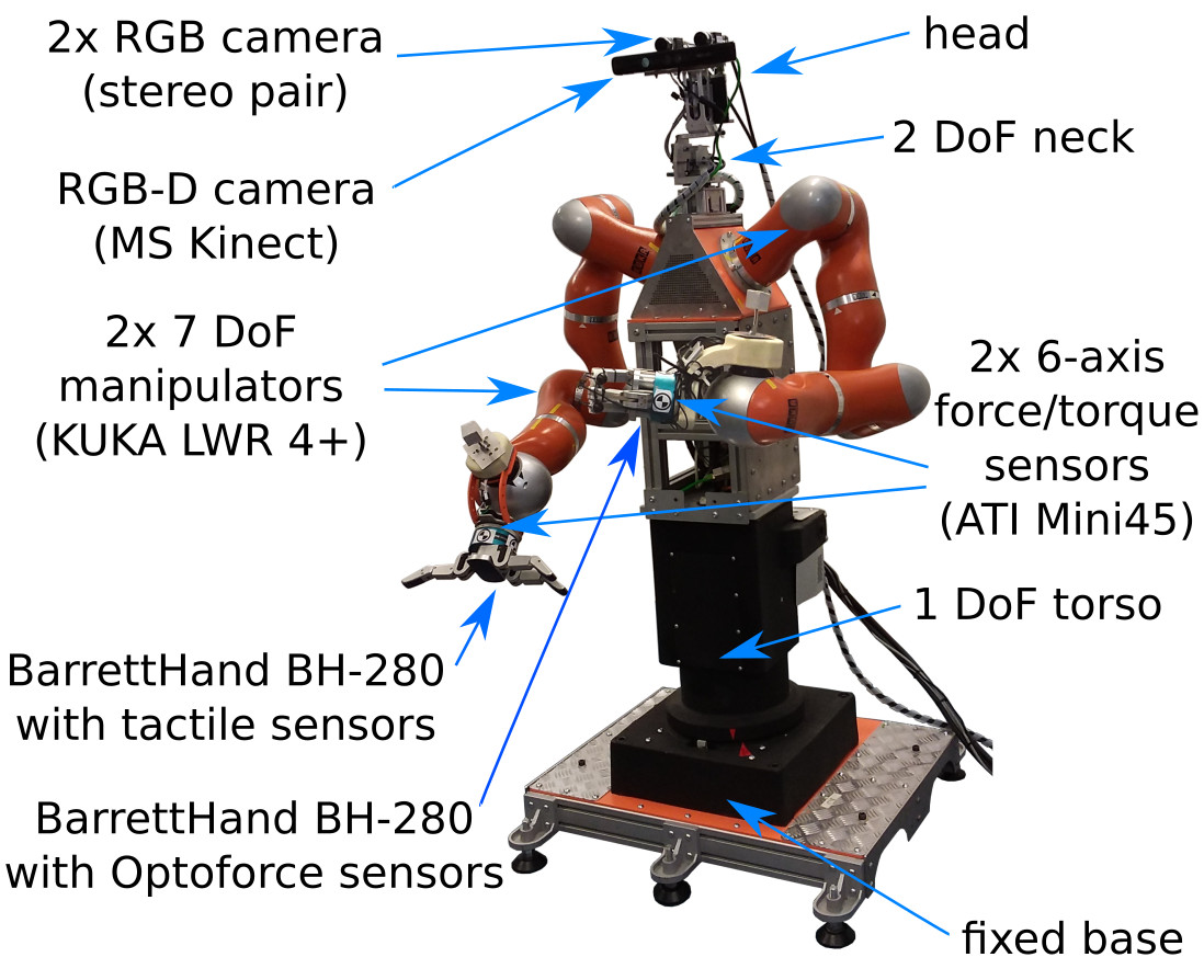
Hardware components
This section presents specification of WUT Velma Robot hardware. The robot is equipped with rotational torso (1 DOF), two arms KUKA LWR (7 DOFs each), two BarrettHand grippers (4 DOFs, 8 joints each) and neck (2 DOFs). The head is equipped with RGB-D camera (Kinect) and stereo pair (two RGB cameras).
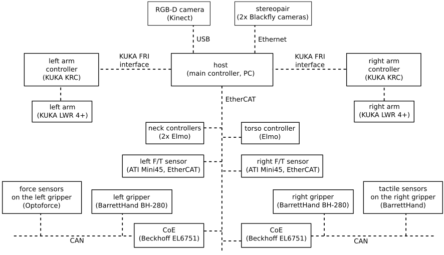
The hardware is connected as shown in the schematic:
Joints
Joint limits:
| joint name | lower limit | upper limit |
|---|---|---|
| torso_0_joint | -1.56 | 1.56 |
| right_arm_0_joint | -2.96 | 2.96 |
| right_arm_1_joint | -2.09 | 2.09 |
| right_arm_2_joint | -2.96 | 2.96 |
| right_arm_3_joint | -2.09 | 2.09 |
| right_arm_4_joint | -2.96 | 2.96 |
| right_arm_5_joint | -2.09 | 2.09 |
| right_arm_6_joint | -2.96 | 2.96 |
| head_pan_joint | -1.57 | 1.57 |
| head_tilt_joint | -1.0 | 1.3 |
The limits for left arm are the same as for the right arm.
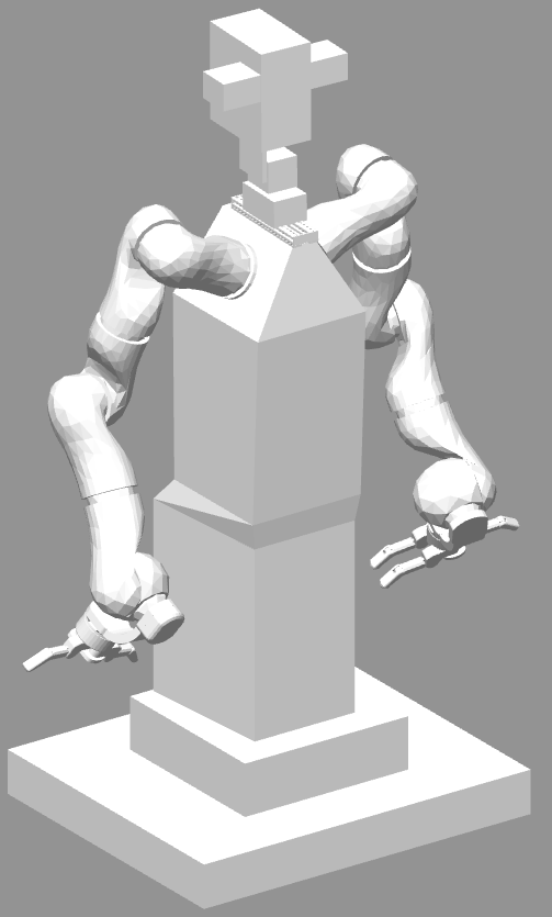
The simulated robot is initialized in configuration presented below. Visualization of the initial configuration:
| joint name | initial position |
|---|---|
| torso_0_joint | 0 |
| right_arm_0_joint | -0.3 |
| right_arm_1_joint | -1.8 |
| right_arm_2_joint | 1.25 |
| right_arm_3_joint | 0.85 |
| right_arm_4_joint | 0 |
| right_arm_5_joint | -0.5 |
| right_arm_6_joint | 0 |
| left_arm_0_joint | 0.3 |
| left_arm_1_joint | 1.8 |
| left_arm_2_joint | -1.25 |
| left_arm_3_joint | -0.85 |
| left_arm_4_joint | 0 |
| left_arm_5_joint | 0.5 |
| left_arm_6_joint | 0 |
Initial position for all other joints (i.e. neck and grippers) is 0.
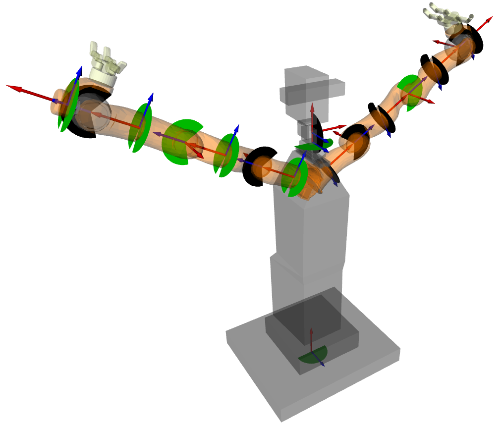
Visualization of some joint axes (red arrows), joint limits (green and black pies) and joint position (blue arrows):
Some joints are position controlled:
- joints of grippers
- joints of neck, i.e. head_pan_joint, head_tilt_joint
Other joints are impedance controlled:
- right arm, i.e. right_arm_X_joint, where \(\scriptsize X\in\{0,1,2,3,4,5,6\}\)
- left arm, i.e. left_arm_X_joint, where \(\scriptsize X\in\{0,1,2,3,4,5,6\}\)
- torso, i.e. torso_0_joint
Example tasks
Please refer to videos at https://www.robotyka.ia.pw.edu.pl/robots/velma.