Reference frames
The local reference frame of the robot is shown in the pictures:
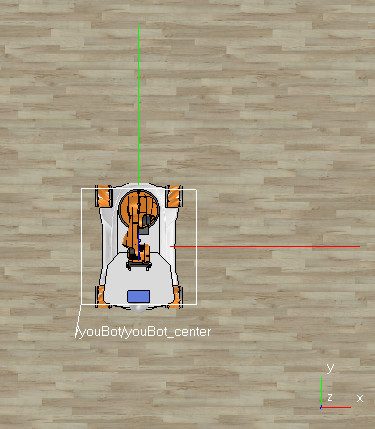
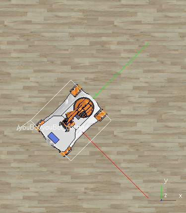
and it is shown as the long red and green lines, centered at the robot center. The red line is for the x axis and green line is for the y axis.
The small frame (short red and green lines) shown in the lower right part of the pictures shows the orientation of the global reference frame.
Please note that the local reference frame of the robot is attached to the robot and it always moves together with the robot, while the global reference frame is attached to the environment and it is fixed (constant).
Variables that control the robot
The robot is controlled from the callback function (described in Example Task page) through three control variables returned by the callback function:
forwBackVel- linear velocity along the y axis of the robot,leftRightVel- linear velocity along the x axis of the robot,rotVel- angular velocity around the z axis of the robot.
The last returned variable finish is a boolean value (true/false) that indicates the control program should be stopped.
The control variables express the commanded velocity in the local frame of the robot.
Current state of the robot
The current pose of the robot in a 2-dimensional plane (XY) can be expressed with three state variables: x, y, and phi. They are available in the callback function through two variables (arguments to the function):
positionis 1x3 vector with x, y and z components. The z component is constant and can be ignored, because the robot moves in XY plane only.orientationis 1x3 vector with psi, theta and phi components. The psi and theta components are constant and can be ignored, because the robot rotates around z axis only.
The state variables are expressed in the global frame.
Controlling the robot in the global frame
To command velocity expressed in the global frame, one must tranfrom the vector to the local reference frame. This is described in detail in Lecture 3.